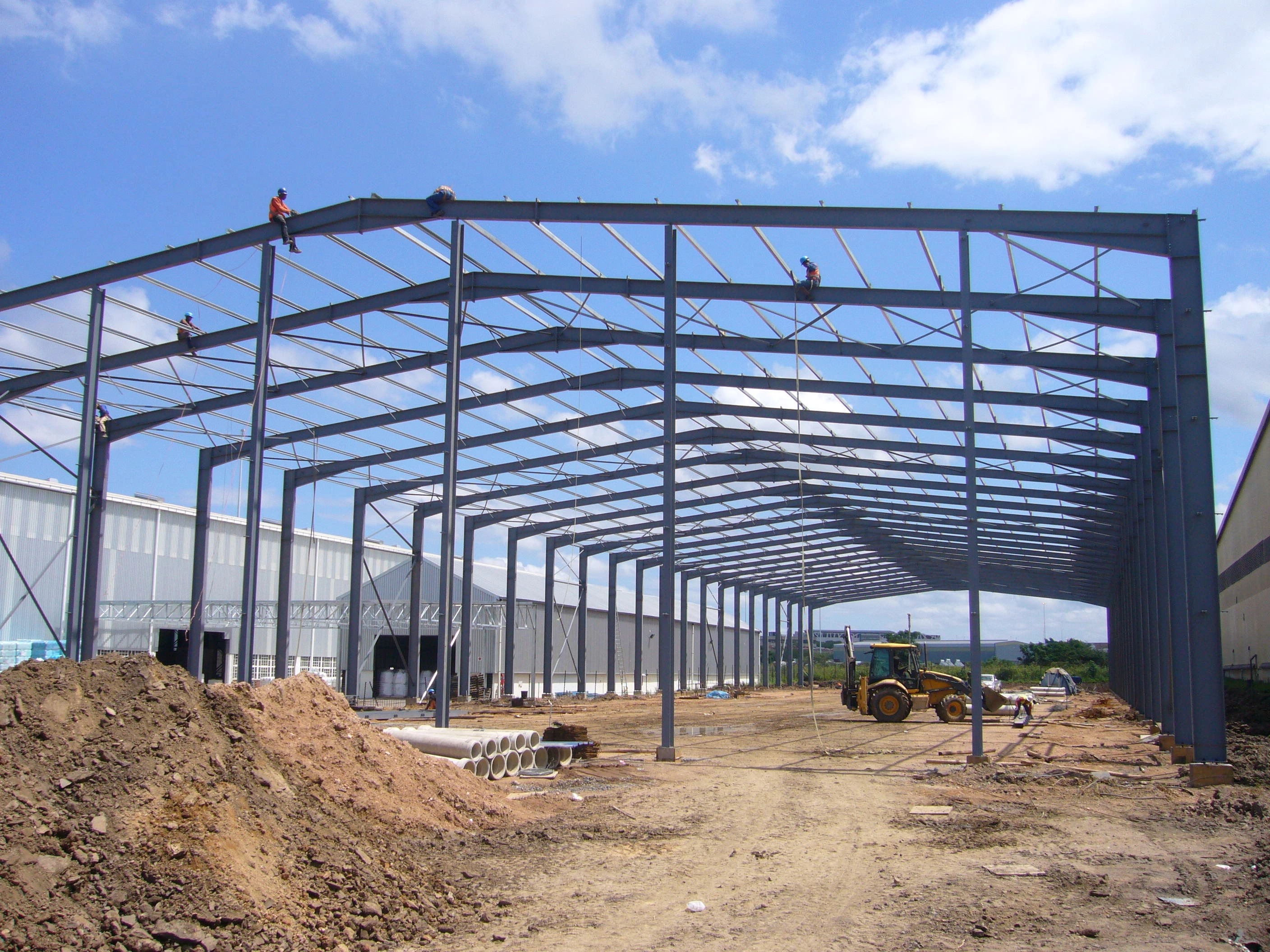
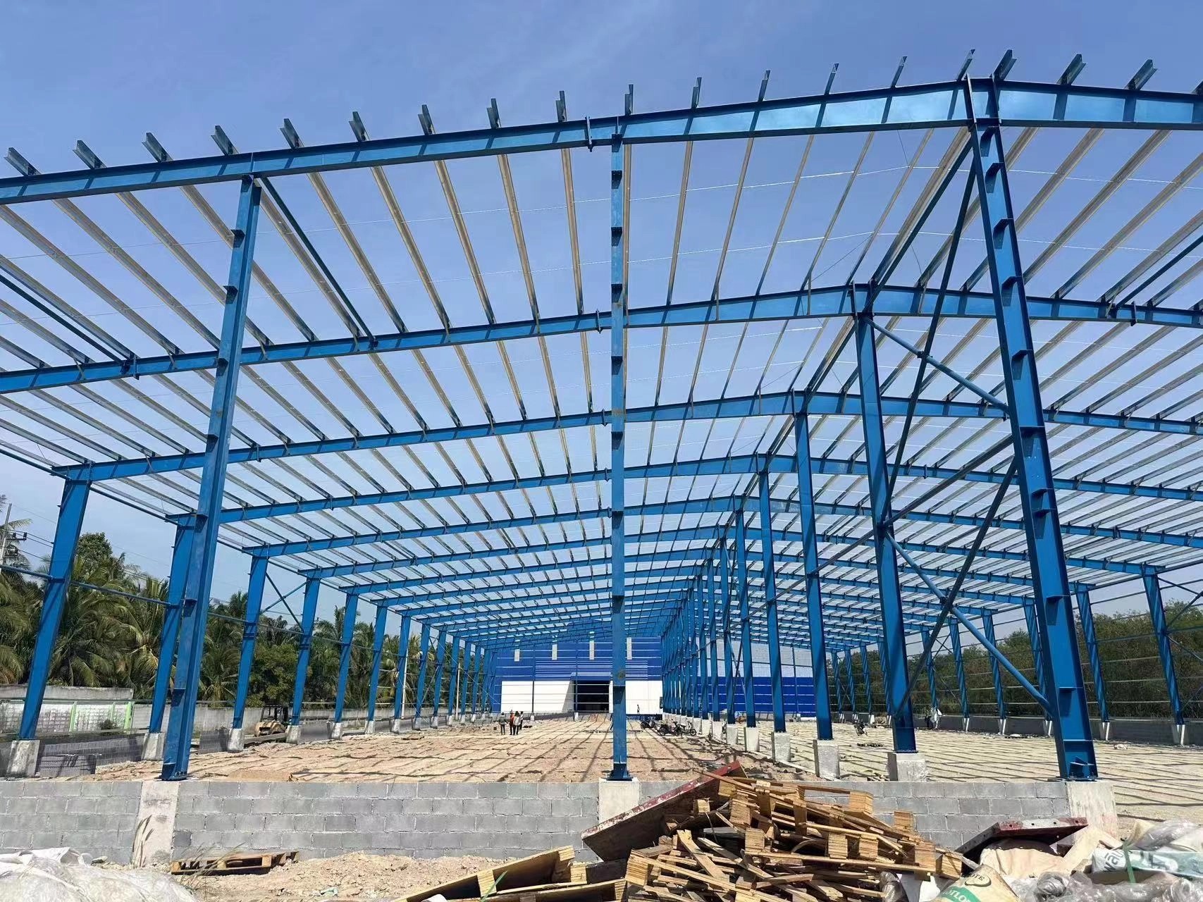
In the world of modern construction, steel structure systems play a critical role in shaping everything from industrial warehouses to skyscrapers. However, the ability to interpret structural steel drawings is just as important as the components themselves. For engineers, architects, and contractors, these drawings act as the blueprint that brings design concepts into reality. Misreading a single symbol or line can lead to costly errors, safety hazards, or project delays. In this article, we'll walk you through how to read structural steel drawings in detail, ensuring you can confidently navigate even the most complex design documents.
Understanding the Importance of Structural Steel Drawings
Structural steel drawings are more than just lines on paper—they are the language of steel structure engineering. These documents translate an architect's vision into precise, buildable instructions for the fabrication and erection of steel components. Every beam, column, bolt, and brace is defined with meticulous detail, including its size, position, connection method, and material specification.
Failure to interpret these correctly could compromise the structural integrity of a building. In essence, structural drawings serve three main purposes:
Design Communication – Clearly convey how the steel structure should be assembled.
Fabrication Guidance – Define dimensions, tolerances, and material grades.
Quality Assurance – Ensure compliance with safety regulations and engineering standards.
Professionals involved in the steel construction process—whether they're welders, site managers, or quality inspectors—must all be literate in this visual language.

Types of Structural Steel Drawings
There are several types of drawings in a steel structure project, each serving a specific function. Let's explore the most common types you'll encounter:
General Arrangement Drawings (GA Drawings)
These show the overall layout of the steel structure. GA drawings include grid lines, floor levels, elevations, and section views. They help you understand where each steel member belongs in the building framework.
Shop Drawings
Shop drawings are highly detailed and focus on individual components. These are created by the fabricator to manufacture steel members precisely. They include bolt holes, welds, and material specs.
Erection Drawings
These are used on-site during the assembly of the steel frame. They include connection details, member positions, and lifting points to ensure safe and efficient erection.
Assembly Drawings
Assembly drawings combine multiple members into a substructure, such as trusses or braced frames. They help welders and fitters know how to assemble sections in the workshop or on-site.
Key Elements Found in Steel Structure Drawings
Each steel structure drawing contains specific notations and symbols. Understanding them is essential to interpreting the design correctly. Here's what you'll usually find:
| Element | Description |
| Beam/Column Labels | Indicate section type and dimensions (e.g., HEB 200, IPE 300) |
| Grid Lines | Help locate structural elements in plan view |
| Elevation Markers | Show height levels of different floors or sections |
| Weld Symbols | Define the type, size, and location of welds |
| Bolt Specifications | Indicate bolt grade, size, and torque requirement |
| Notes & Legends | Clarify material specifications, tolerances, and other important instructions |
Let's take a deeper look into some of these.
Steel Member Labeling
Each steel element is labeled using a standardized system. For instance, “IPE300” refers to an I-shaped European steel section with a depth of 300mm. This notation helps fabricators select the correct profile without confusion.
Weld and Bolt Details
Weld symbols might include fillet, groove, or spot welds, each with a corresponding symbol on the drawing. Similarly, bolt details often include symbols for snug-tight or pre-tensioned bolts, as well as specifications for washers and nuts.
How to Read Connection Details
Connection details are critical in steel structure drawings because they dictate how different members interact and transfer loads. Here's a systematic approach to reading them:
Identify Connection Type
There are typically three main types:
Bolted connections (slip-critical or bearing type)
Welded connections (site or shop welds)
Hybrid connections (a combination of both)
The drawing will specify whether the connection is moment-resisting, pinned, or braced, and how it should be executed.
Review Fastener Callouts
Callouts like “M20 8.8” refer to a 20mm diameter bolt of strength grade 8.8. Such specifications ensure load-bearing capacity is met without over-engineering.
Examine Plate Thicknesses
Plates such as base plates, end plates, and gusset plates will have thickness, length, and hole positioning marked. Ensure these match the specifications for load transfer and alignment.

Common Challenges When Interpreting Steel Structure Drawings
Even seasoned professionals can encounter difficulties when reading steel structure drawings. Here are some common challenges and how to overcome them:
Confusing Symbols or Abbreviations
Solution: Always refer to the drawing legend or general notes section. If absent, consult relevant standards such as AISC or Eurocode.
Misalignment in Elevations or Sections
Solution: Cross-reference multiple views (plan, elevation, and section) to resolve conflicts. Structural elements often span different planes and misreading one can cause dimensional inaccuracies.
Misinterpretation of Scale
Solution: Always check the scale indicated on the drawing. Use architectural rulers or CAD software to measure dimensions accurately.
FAQs About Reading Steel Structure Drawings
Here are some frequently asked questions that may help you further understand the process:
Do I need engineering software to read steel structure drawings?
Not necessarily. While software like AutoCAD or Tekla Structures can enhance interpretation, hard-copy prints are still widely used on construction sites. Basic engineering literacy and a good ruler are often enough.
Can I read steel drawings without engineering training?
You can learn the basics, but for safety-critical projects, interpretation should be done or reviewed by licensed professionals.
What should I do if I find a discrepancy in the drawing?
Immediately escalate the issue to the responsible design engineer or structural consultant. Never proceed with fabrication or construction if there's uncertainty.
Are 2D drawings enough for complex steel structures?
For simpler buildings, yes. But for complex or high-rise projects, 3D modeling (BIM) is increasingly used to reduce ambiguity and improve coordination.
Conclusion
Mastering how to read structural steel drawings is a vital skill for anyone involved in steel structure construction. These drawings form the bridge between design and reality, translating complex architectural concepts into physical structures. A misread dimension or overlooked weld symbol might seem trivial on paper, but it can have serious implications on site.
Take the time to familiarize yourself with the different drawing types, symbols, scales, and conventions. As you gain more experience, interpreting these intricate blueprints will become second nature, empowering you to execute projects with precision and confidence.


